Difference between revisions of "Cyclones"
(Created page with "Category:Separating{{Knoppen}} <noinclude><!------------------------------------------------ * READ THIS FIRST * Only edit this page if you can improve the content. * Improp...") |
|||
| (2 intermediate revisions by 2 users not shown) | |||
| Line 7: | Line 7: | ||
* Please start editing this page after the /noinclude | * Please start editing this page after the /noinclude | ||
* -------------------------------------------------></noinclude> | * -------------------------------------------------></noinclude> | ||
This | [[File:Cyclone_seperator.png|thumb|right|Cyclone seperator]] | ||
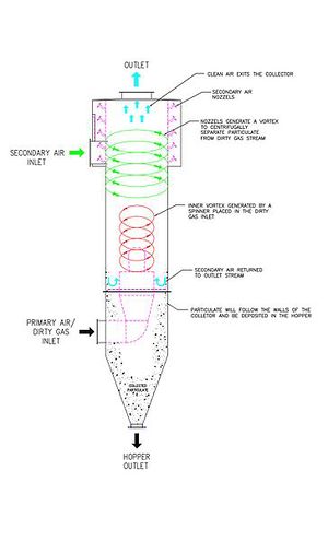
[[File:Vertical-cyclone.jpg|thumb|right|Airflow diagram for a cyclone in standard vertical position. Secondary air flow is injected to reduce wall abrasion.]] | |||
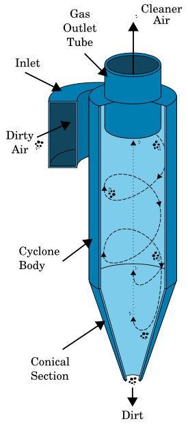
'''Cyclones''' use a method called cyclonic separation. It removes solid particulates from an air, gas or liquid stream, without the use of filters, through vortex separation. Rotational effects and gravity are used to separate mixtures of solids and fluids. The method can also be used to separate fine droplets of liquid from a gaseous stream. | |||
A high speed rotating (air)flow is established within a cylindrical or conical container called a cyclone. Air flows in a helical pattern, beginning at the top (wide end) of the cyclone and ending at the bottom (narrow) end before exiting the cyclone in a straight stream through the center of the cyclone and out the top. Larger (denser) particles in the rotating stream have too much inertia to follow the tight curve of the stream, and strike the outside wall, then falling to the bottom of the cyclone where they can be removed. In a conical system, as the rotating flow moves towards the narrow end of the cyclone, the rotational radius of the stream is reduced, thus separating smaller and smaller particles. The cyclone geometry, together with flow rate, defines the cut point of the cyclone. This is the size of particle that will be removed from the stream with a 50% efficiency. Particles larger than the cut point will be removed with a greater efficiency, and smaller particles with a lower efficiency. | |||
Airflow diagram for a cyclone in standard vertical position. Secondary air flow is injected to reduce wall abrasion. Airflow diagram for a cyclone in horizontal position, an alternate design. Secondary air flow is injected to reduce wall abrasion, and to help move collected particulates to hopper for extraction. | |||
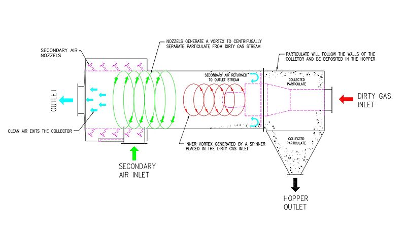
An alternative cyclone design uses a secondary air flow within the cyclone to keep the collected particles from striking the walls, to protect them from abrasion. The primary air flow containing the particulates enters from the bottom of the cyclone and is forced into spiral rotation by stationary spinner vanes. The secondary air flow enters from the top of the cyclone and moves downward toward the bottom, intercepting the particulate from the primary air. The secondary air flow also allows the collector to optionally be mounted horizontally, because it pushes the particulate toward the collection area, and does not rely solely on gravity to perform this function. | |||
Large scale cyclones are used in sawmills to remove sawdust from extracted air. Cyclones are also used in oil refineries to separate oils and gases, and in the cement industry as components of kiln preheaters. Cyclones are increasingly used in the household, as the core technology in bagless types of portable vacuum cleaners and central vacuum cleaners. Cyclones are also used in industrial and professional kitchen ventilation for separating the grease from the exhaust air in extraction hoods.[1] Smaller cyclones are used to separate airborne particles for analysis. Some are small enough to be worn clipped to clothing, and are used to separate respirable particles for later analysis. | |||
Analogous devices for separating particles or solids from liquids are called hydrocyclones or hydroclones. These may be used to separate solid waste from water in wastewater and sewage treatment. | |||
[[File:Horizontal-cyclone.jpg]] | |||
Airflow diagram for a cyclone in horizontal position, an alternate design. Secondary air flow is injected to reduce wall abrasion, and to help move collected particulates to hopper for extraction. | |||
Latest revision as of 03:34, 27 September 2012
Cyclones use a method called cyclonic separation. It removes solid particulates from an air, gas or liquid stream, without the use of filters, through vortex separation. Rotational effects and gravity are used to separate mixtures of solids and fluids. The method can also be used to separate fine droplets of liquid from a gaseous stream.
A high speed rotating (air)flow is established within a cylindrical or conical container called a cyclone. Air flows in a helical pattern, beginning at the top (wide end) of the cyclone and ending at the bottom (narrow) end before exiting the cyclone in a straight stream through the center of the cyclone and out the top. Larger (denser) particles in the rotating stream have too much inertia to follow the tight curve of the stream, and strike the outside wall, then falling to the bottom of the cyclone where they can be removed. In a conical system, as the rotating flow moves towards the narrow end of the cyclone, the rotational radius of the stream is reduced, thus separating smaller and smaller particles. The cyclone geometry, together with flow rate, defines the cut point of the cyclone. This is the size of particle that will be removed from the stream with a 50% efficiency. Particles larger than the cut point will be removed with a greater efficiency, and smaller particles with a lower efficiency.
Airflow diagram for a cyclone in standard vertical position. Secondary air flow is injected to reduce wall abrasion. Airflow diagram for a cyclone in horizontal position, an alternate design. Secondary air flow is injected to reduce wall abrasion, and to help move collected particulates to hopper for extraction.
An alternative cyclone design uses a secondary air flow within the cyclone to keep the collected particles from striking the walls, to protect them from abrasion. The primary air flow containing the particulates enters from the bottom of the cyclone and is forced into spiral rotation by stationary spinner vanes. The secondary air flow enters from the top of the cyclone and moves downward toward the bottom, intercepting the particulate from the primary air. The secondary air flow also allows the collector to optionally be mounted horizontally, because it pushes the particulate toward the collection area, and does not rely solely on gravity to perform this function.
Large scale cyclones are used in sawmills to remove sawdust from extracted air. Cyclones are also used in oil refineries to separate oils and gases, and in the cement industry as components of kiln preheaters. Cyclones are increasingly used in the household, as the core technology in bagless types of portable vacuum cleaners and central vacuum cleaners. Cyclones are also used in industrial and professional kitchen ventilation for separating the grease from the exhaust air in extraction hoods.[1] Smaller cyclones are used to separate airborne particles for analysis. Some are small enough to be worn clipped to clothing, and are used to separate respirable particles for later analysis.
Analogous devices for separating particles or solids from liquids are called hydrocyclones or hydroclones. These may be used to separate solid waste from water in wastewater and sewage treatment.
Airflow diagram for a cyclone in horizontal position, an alternate design. Secondary air flow is injected to reduce wall abrasion, and to help move collected particulates to hopper for extraction.


